What are the common forging tolerances for shafts and flanges?
For engineers, OEM buyers, and procurement teams, dimensional tolerance is one of the first technical issues to clarify when sourcing forged components. In shaft forging tolerance determines how closely the forged blank can conform to the specified dimensions before machining, while flange forgings must also maintain control over features such as outside diameter, thickness, bolt-hole locations, and face geometry. However, there is not one “standard forging tolerance” for all shafts or flanges. The possible tolerance relies on the material grade, forging method, component size, die design, forging temperature, heat treatment, machining allowance and the dimensional specifications written on the drawing. For example, a large open die forged shaft should not be judged against the same dimensions requirements as a tiny closed die forge. It is also necessary to distinguish between as-forged dimensions and final machined dimensions. Forging is often meant to create a good near completed blank, with sufficient material to allow later machining, rather than to substitute for precision machining entirely. For example , ASTM A668/A668M includes carbon and alloy steel forgings for general industrial use . There are also application-specific forging specifications for pressure vessels , turbine components , shafts and other essential parts . Flanges used in piping systems have their dimensions, tolerances, materials, ratings, labelling and testing specified in standards such as ASME B16.5. The applicable requirement, however, is still dependent upon the type, size, pressure class, material and purchase specification of the flange. Knowing these variances will assist buyers to specify realistic needs, and will help manufacturers to select a suitable forging technique without adding extra production expense.
What determines the dimensional tolerance of a forged shaft?
Material grade and forging behavior
The first aspect to consider in establishing feasible dimensional accuracy is the material to be forged. Carbon steel, alloy steel, stainless steel, aluminum alloys, and titanium alloys have varying flow stress, ductility, thermal reactivity, and forging temperature ranges and behave differently during deformation.
For a shaft, forging, these qualities are affecting the consistency of material filling the die or movement beneath the forging tools. They also influence the amount of dimensional change that occurs during cooling and heat treatment.
For example, a large alloy steel shaft may require considerable forging force and controlled heat treatment. Residual tensions can be alleviated after forging and cause dimensional changes after cooling or heat treatment. The final inspection, therefore, must not rely solely on the dimensions after forging.
The right way is to define the needed tolerance, the material grade, and the manufacturing route. For example, a drawing for a final machined diameter should also provide adequate stock for machining if the part is delivered as forged.
The forging method has a major influence.
Dimensional correctness of the forging process is quite sensitive.
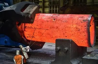
Open-die forging is generally used for big shafts, rings, blocks, and other heavy components. It provides a great deal of flexibility in the size and shape of the component, but the dimensional control of an as-forged surface normally is less exact than that of a closely controlled closed-die process.
Closed die forging uses shaped dies to regulate the flow of material, offering higher reproducibility for acceptable component geometries and production quantities. But you have to consider the die cost, the part geometry, the flow of material, flash creation, and draft requirements.
For big shaft forgings, the makers may use many forging procedures instead of trying to achieve the final geometry in a single operation. This method can improve the distribution of materials and reduce the variation caused by deformation.
So, requesting a supplier for a single universal tolerance without indicating the forging method can result in false comparisons.
Forging temperature and thermal contraction
Another crucial concern is temperature management.
Hot forging grows as it heats and shrinks as it cools. The magnitude of change of dimension is dependent on the material, size of the component, forging temperature, cooling conditions, and subsequent heat treatment.
Temperature differences between surface and core can also influence the deformation behavior in the case of long bodies or large shaft cross-sections. If the temperature is not regulated uniformly, the dimensions may fluctuate from one portion of the component to another.
Hence, a steady forging temperature window allows the makers to control repeatability. However, tighter dimensional control does not just mean to use a greater or lower forging temperature. It must be set to the right range for the individual material and forging process.
Die condition and tool wear
Die condition can have a direct effect on dimensional consistency for closed-die shaft forging and flange forgings.
A new, correctly machined die may more consistently repeat the specified shape than a worn die. As production proceeds, wear can slowly modify essential dimensions, especially on features subject to high contact pressure or repetitive material flow.
Therefore, manufacturers need to monitor the state of dies and set criteria for maintenance or replacement. For high-volume production, die wear control might be as crucial as the initial die design.
What are the typical tolerance considerations for shaft forgings?
Diameter, length, straightness, and concentricity
Shaft forgings frequently have many important dimensional parameters rather than one overall tolerance.
The most prevalent ones are
-
O.D.
-
Total Length
-
Step or shoulder width
-
Linearity
-
Coaxiality or concentricity between parts
-
Face dimensions
-
Allowance for machining
-
Surface status
The diameter is especially essential since a large percentage of forged shafts are then machined to create bearing seats, gear seats, journals, or coupling interfaces.
Also, for long shafts, accumulated dimensional variation might impair subsequent machining and assembly; therefore, dimensional tolerance is critical.
In long members, straightness is of particular importance. A shaft can be OK in local diameters, but if it has too much bow or runout, it may need to be corrected or machined further.
These constraints should be stated explicitly and not buried in a broad statement like “tight forging tolerance."
Why does machining allowance matter?
Forged shafts are frequently supplied with additional material that will later be removed by turning, milling, grinding, or other machining processes.
This material is known as machining allowance or stock allowance.
The allowance needs to be large enough to remove surface irregularities, scale, local dimensional variation, and other material left from forging while still allowing the final component to reach its drawing dimensions.
Too little allowance can create a machining problem because the finished surface may not clean up completely. Too much allowance increases material removal, machining time, tooling consumption, and overall cost.
For this reason, a practical purchasing specification should distinguish between:
-
the required as-forged dimensions;
-
the required machining allowance; and
-
the final machined dimensions.
This distinction is particularly important when comparing quotations from different forging suppliers.
How do flange forging tolerances differ from shaft forging tolerances?
Flanges require control of several geometric features.
A flange is different from a simple cylindrical shaft because its function often depends on several dimensions working together.
Depending on the flange design, important features can include:
-
Outside diameter
-
Overall thickness
-
Hub diameter
-
Bore diameter
-
Raised-face dimensions
-
Bolt-hole diameter
-
Bolt-hole spacing
-
Bolt-circle diameter
-
Flatness
-
Parallelism
-
Concentricity
A dimensional error in one feature of a shaft forging may affect the assembly even if other dimensions remain within specification.
For example, a flange may have the correct outside diameter but still create an assembly problem if the bolt-hole pattern is incorrectly positioned. Similarly, an acceptable thickness does not automatically mean that the sealing face has the required flatness.
This is why flange inspection should consider both dimensional tolerances and geometric tolerances.
Flange standards should be identified before production.
When a forged flange is intended for a standardized piping application, the applicable flange standard should be identified before manufacturing begins.
ASME B16.5 is one important example. It covers pipe flanges and flanged fittings within defined NPS size and pressure-class ranges and includes requirements relating to dimensions and tolerances as well as other technical requirements.
However, the standard for the finished flange should not automatically be treated as a universal tolerance specification for the raw forging.
The forging drawing may specify additional requirements for:
-
Forging dimensions
-
Heat treatment
-
Material grade
-
Ultrasonic testing
-
Surface quality
-
Machining allowance
-
Identification and traceability
-
Final machined dimensions
The manufacturer should therefore review the complete drawing and purchase specification rather than selecting a tolerance based only on the flange's nominal size.
Post-forging machining usually provides the final precision
Forging establishes the basic shape and metallurgical structure, but precision machining is normally responsible for achieving the tightest final dimensions.
A forged flange may therefore be produced with additional stock and then machined on a lathe, milling machine, boring machine, or other equipment.
This is particularly relevant to sealing faces and bolt-hole patterns. If the final assembly requires precise positioning, the machining process must be designed around the datum structure and inspection requirements of the finished component.
In other words, forging tolerance and machining tolerance should not be treated as the same thing.
Which standards and specifications should buyers consider?
ASTM specifications for steel forgings
ASTM specifications can define material, manufacturing, heat treatment, testing, and other requirements for particular categories of forgings.
ASTM A668/A668M, for instance, covers untreated and heat-treated carbon and alloy steel forgings for general industrial use. It includes different material classes and mechanical-property requirements.
Other ASTM forging specifications address more specialized applications. ASTM's current steel standards catalogue includes specifications for pressure vessel forgings, turbine rotor forgings, stainless steel forgings, and other specialized products.
The important point is that the applicable standard should be selected according to the component's material and application instead of assuming that one specification covers every shaft forging or flange.
ASME requirements for finished flanges
For flanges and flanged fittings used in piping systems, ASME B16.5 can be relevant because it covers dimensions, tolerances, pressure-temperature ratings, materials, marking, and testing for the products within its scope.
This makes it especially important to identify whether the customer is purchasing:
-
an as-forged blank,
-
a rough-machined forging,
-
or a fully finished flange.
The dimensional requirements can differ significantly between these stages.
How can manufacturers achieve more consistent forging tolerances?
Use process simulation before production.
Modern forging simulation can help engineers predict material flow, deformation, die filling, and areas where dimensional variation may occur.
Finite element analysis (FEA) can be useful for large or complicated components because it allows engineers to evaluate the forming sequence before committing to production tooling.
For shaft forging, simulation can help assess whether the selected forging sequence will produce sufficient material distribution along the shaft. For flange forgings, it can help identify areas where the material may not fill the die uniformly.
Simulation does not eliminate the need for physical trials, but it can reduce unnecessary trial-and-error work.
Control the forging sequence and temperature.
Consistent results require more than accurate dies. The complete process should be controlled.
Important variables include:
-
Billet or starting-stock dimensions
-
Heating temperature
-
Soaking time
-
Forging temperature
-
Reduction per operation
-
The alignment
-
Cooling conditions
-
Heat-treatment cycle
-
Straightening operations
Controlling these variables helps reduce variation between production batches.
For large shafts, particular attention should be paid to thermal uniformity and deformation throughout the component. A process that produces good results on a small test piece may require different controls when the forging size increases substantially.
Combine dimensional inspection with process control.
Final inspection should verify the features that matter to assembly and machining.
Depending on the component, manufacturers may use:
-
Vernier calipers and micrometers for basic dimensions
-
Bore gauges for internal diameters
-
Dial indicators for runout and straightness
-
CMMs for complex dimensional inspection
-
Optical or laser measurement systems for selected geometries
-
Ultrasonic testing for internal discontinuities
-
Magnetic particle testing for suitable ferromagnetic materials
CMM inspection can be particularly useful when several flange features must be evaluated against common datums.
However, dimensional inspection and nondestructive testing serve different purposes. A CMM can verify geometry, while ultrasonic testing can help identify certain internal discontinuities. Neither should be treated as a substitute for the other.
Conclusion
There is no single tolerance value that can be applied to every forged shaft or flange. The appropriate tolerance depends on the material, forging method, component size, geometry, die design, thermal conditions, heat treatment, machining allowance, applicable standard, and final application.
For shaft forging, buyers should pay particular attention to diameter, length, straightness, concentricity, and the amount of machining stock available for subsequent operations. For flange forgings, outside diameter, thickness, bore, bolt-hole location, bolt-circle dimensions, face geometry, and other geometric characteristics may all affect assembly performance.
Standards can provide an important framework, but they should be applied according to the actual product and supply stage. ASTM A668/A668M, for example, addresses general industrial steel forgings, while ASME B16.5 covers specified pipe flanges and flanged fittings and includes dimensional and tolerance requirements within its scope.
The most reliable approach is therefore to define the as-forged tolerance, machining allowance, and final machined tolerance separately. When manufacturers combine controlled forging parameters, suitable tooling, heat-treatment control, machining, and dimensional inspection, they can produce shafts and flanges that meet the functional requirements without imposing unnecessarily tight and costly forging tolerances.
Your Custom Metal Parts Partner: Quality Forged, Cast & Machined
Shaanxi Welong Int'l Supply Chain Mgt Co., Ltd., established in 2001, is a leading provider of customized metal parts for various industries. With certifications including ISO 9001:2015 and API-7-1, we specialize in forging, casting, and machining processes. Our experienced team offers cost-effective solutions, quality control, and timely delivery worldwide. With a track record of serving over 100 customers across Europe, North America, and Asia, we strive to be at the forefront of international supply chain management and Chinese intelligent manufacturing. Our diverse product range includes sand casting, investment casting, centrifugal casting, die casting, and both open and closed die forging in various materials. For expert assistance with your metal part needs, contact us at info@welongpost.com.
FAQ
1: What are the typical tolerance ranges for forged shafts?
Typical tolerance ranges for forged shafts can vary depending on the size and material, but generally fall within ±0.5mm to ±2mm for diameter and length dimensions.
2: How do flange forging tolerances compare to shaft tolerances?
Flange forging tolerances are often tighter than shaft tolerances due to their more complex geometry and critical sealing surfaces, typically ranging from ±0.2mm to ±1mm for critical dimensions.
3: What factors most significantly affect forging tolerances?
The most significant factors affecting forging tolerances include material properties, forging temperature, die design, and the specific forging process used.
4: Can post-forging operations improve tolerance accuracy?
Yes, post-forging operations such as machining, heat treatment, and surface finishing can significantly improve tolerance accuracy, often achieving tighter tolerances than forging alone.
References
1. Smith, J. R. (2018). Advanced Forging Techniques for Precision Components. Journal of Materials Processing Technology, 256, 112-124.
2. Johnson, A. B., & Brown, C. D. (2019). Tolerance Control in Shaft and Flange Forging: A Comprehensive Review. International Journal of Precision Engineering and Manufacturing, 20(8), 1365-1382.
3. Thompson, R. L. (2020). Innovations in Die Design for Improved Forging Tolerances. Forging Magazine, 31(4), 28-35.
4. Davis, E. M., & Wilson, G. H. (2017). The Impact of Material Properties on Forging Tolerances. Materials Science and Engineering: A, 701, 215-228.
5. Anderson, K. L. (2021). Quality Control Techniques for High-Precision Forged Components. Journal of Manufacturing Systems, 58, 123-137.
6. Lee, S. Y., & Park, J. W. (2019). Simulation-Based Optimization of Forging Processes for Enhanced Dimensional Accuracy. Computers & Industrial Engineering, 135, 1092-1104.

Share your inquiry, get the quotation accordingly!

China WELONG- Your Reliable Partner in Metal Solutions