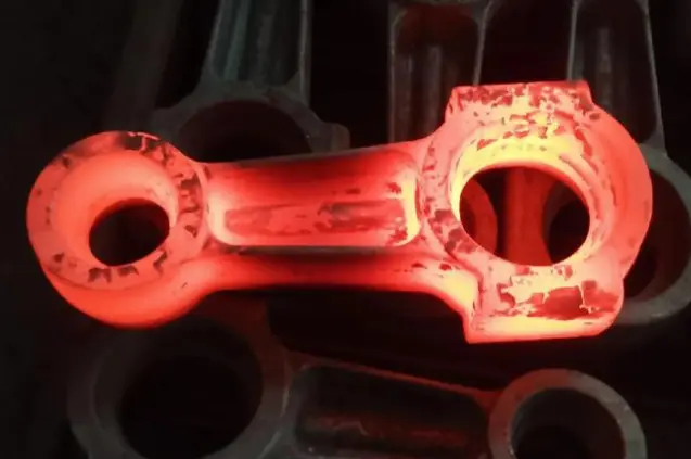
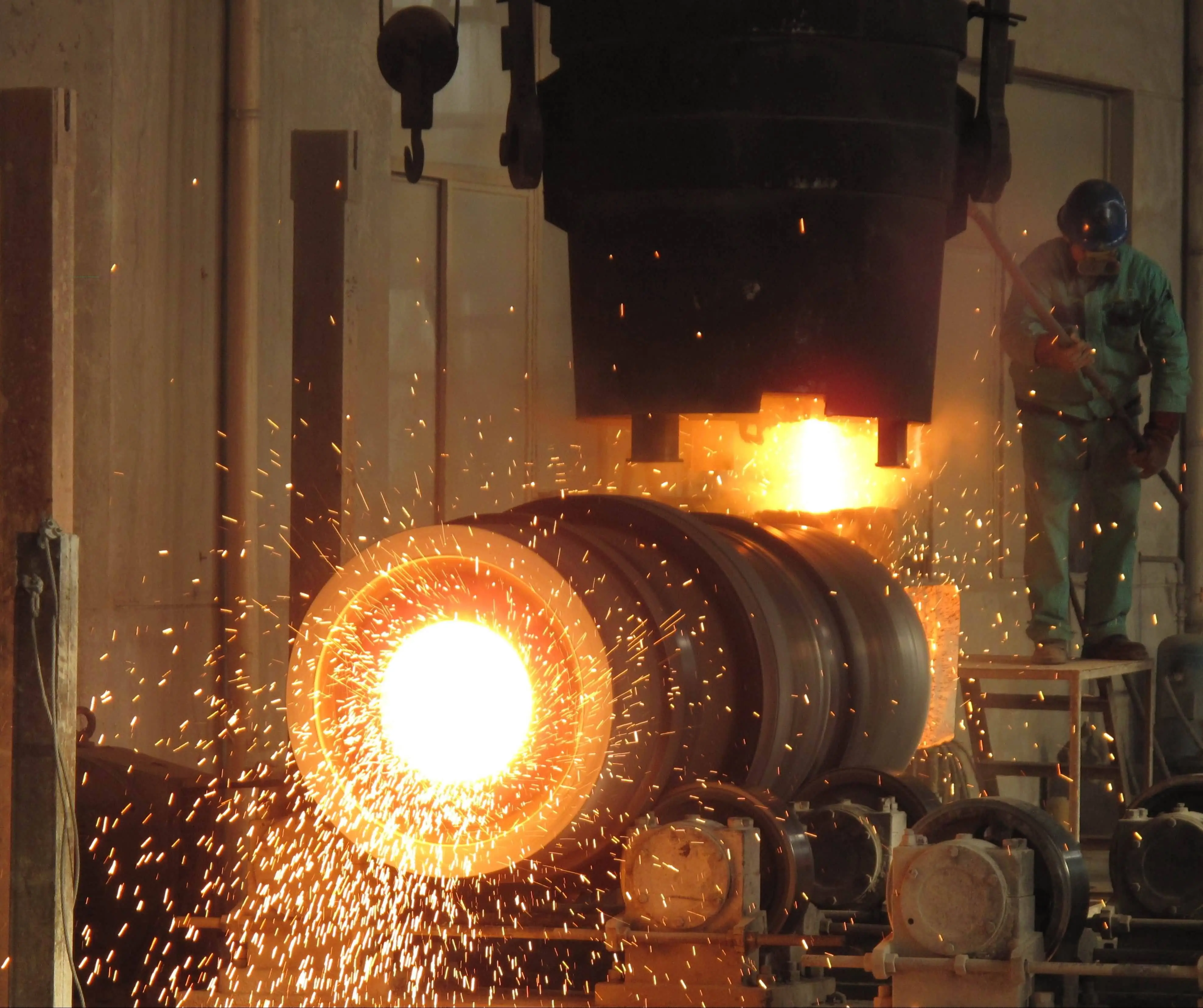
How to reduce defects like flash in closed die forging?
Flash is a normal part of many closed die forging operations, but excessive or poorly controlled flash can increase material consumption, trimming requirements, die wear, and production costs. For manufacturers producing precision components in medium- or high-volume production, controlling flash is therefore an important part of process optimization rather than simply removing it after forging. In a well-designed closed die forging process, a controlled amount of flash can help build pressure inside the die cavity and support complete filling of difficult sections. The objective is not necessarily to eliminate flash completely. Instead, manufacturers should control its location, thickness, volume, and consistency while ensuring that the forging cavity is properly filled. Flash problems can result from several interacting factors, including billet volume, material temperature, preform geometry, die design, lubrication, press conditions, and die wear. Addressing only one parameter may not solve the problem if another part of the process is causing excessive material flow. For this reason, manufacturers should evaluate flash together with part geometry, dimensional tolerances, material utilization, and forging stability. The following sections explain the main causes of excessive flash and practical methods for reducing it in closed die forging production.
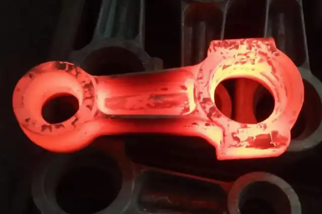
What causes excessive flash in closed die forging?
Incorrect billet volume and weight
The amount of material entering the die has a direct influence on flash formation. If the billet contains more material than required for the finished forging and the designed flash allowance, the excess material must move somewhere as the die closes. This can produce a thicker or wider flash.
Billet weight should therefore be established from the required forging volume, flash allowance, trimming allowance, and expected process losses. Weight variation between billets can also create inconsistent results from one forging to another.
For production parts with tight dimensional requirements, controlling billet weight within an appropriate tolerance can be more effective than trying to correct excessive flash later through trimming.
However, reducing billet volume too aggressively is not a solution. An undersized billet may cause incomplete die filling, underfilled sections, laps, or dimensional problems. The objective is to establish the correct material volume for the complete forging sequence.
Inconsistent billet temperature
Forging temperature affects material flow stress and deformation behavior. If billets enter the die at inconsistent temperatures, the same die and press settings may produce different filling patterns.
A billet that is too cold may require higher forming force and may not flow sufficiently into thin or complicated sections. A billet that is excessively hot may experience increased oxidation, surface degradation, or undesirable changes in material behavior.
Temperature uniformity is therefore more important than simply selecting a high forging temperature. Manufacturers should control heating time, furnace conditions, transfer time, and temperature differences between the billet surface and core where applicable.
For repeat production, temperature measurement and process records can help identify whether abnormal flash is related to inconsistent heating rather than die geometry.
Poor performance or blocker design
For complicated components, the final die should not always be expected to perform all of the material distribution in one operation. A preform or blocker may be required to place material closer to the regions where it will be needed during final forging.
An unsuitable preform can force excessive material toward the parting line, increasing flash while leaving other areas difficult to fill. A well-designed preform distributes material more efficiently before the final cavity is closed.
This is one reason why flash reduction should be considered at the process-planning stage. If the material distribution problem originates in an earlier operation of closed die forging, simply changing the final flash land may not provide a reliable solution.
How can die design reduce flash?
Optimize the parting line.
The position of the die parting line affects how material flows during forging. A poorly selected parting line can encourage material to move toward the flash region instead of filling critical areas of the cavity.
Engineers should consider the component geometry, expected grain flow, draft, undercuts, machining allowances, and trimming requirements when selecting the parting line.
For complex forgings, simulation can help compare different parting-line arrangements before the die is manufactured. This reduces the risk of discovering major filling or flash problems after production tooling has already been completed.
Control flash land dimensions.
The flash land is an important feature of many closed-die forging dies. Its geometry influences resistance to material flow and therefore contributes to the pressure generated inside the die cavity.
If the flash land is not properly designed, material may escape too easily, reducing the pressure available for cavity filling. Conversely, excessive resistance can increase forming loads and accelerate die wear.
The appropriate geometry depends on the material, component size, forging temperature, press capability, and part design. Manufacturers should therefore avoid treating flash land dimensions as a universal value that can be applied to every forging.
Instead, the flash land should be designed as part of the complete material-flow system.
Design the gutter for effective flash containment.
The gutter provides space for excess material to flow after the cavity has been filled. Its purpose is not simply to collect scrap. Proper gutter design can help regulate flash formation and prevent uncontrolled material flow around the die parting line.
The gutter should provide sufficient volume for the expected flash while remaining compatible with trimming requirements. Its geometry also needs to account for how the flash will be removed after forging.
When excessive flash repeatedly appears in the same area, engineers should inspect both the flash land and gutter rather than assuming that the problem is caused only by billet volume.
Which process parameters should be controlled?
Maintain the appropriate forging temperature.
Temperature should be selected according to the material and forging process rather than increased simply to improve flow.
The appropriate temperature range can reduce forming resistance while maintaining acceptable material properties and surface condition. Temperature should also remain reasonably consistent from billet to billet.
In production, manufacturers can monitor furnace settings, billet heating time, transfer time, and forging temperature to identify trends. If flash changes significantly during a production run, temperature variation should be considered alongside die wear and lubrication.
Control press speed and forming conditions
Press speed influences deformation behavior, heat generation, material flow, and cycle time. Depending on the equipment and material, changing the forming rate can alter how quickly the cavity fills and how much material is forced into the flash region.
Mechanical presses, hydraulic presses, and other forging equipment have different operating characteristics. Therefore, process parameters should be established based on the actual equipment and component rather than copied from another forging line.
Stable press operation is especially important for high-volume production. Variations in stroke, energy, closing position, or alignment can contribute to inconsistent flash dimensions.
Improve lubrication consistency.
Lubrication affects friction between the workpiece and die surfaces. If friction conditions change significantly during production, material flow can also change.
Insufficient or uneven lubricant coverage may restrict material movement in some areas and promote excessive flow toward others. Excessive lubricant can create other process problems and should not be treated as automatically beneficial.
A controlled lubrication procedure should specify the lubricant type, application method, concentration where relevant, coverage, and application frequency. Consistency is particularly important when comparing samples during process qualification.
How can simulation help reduce flash before production?
Use finite element analysis to predict material flow.
Finite Element Analysis (FEA) can provide useful information before physical tooling trials begin. Depending on the simulation system and input data, engineers can evaluate material flow, forming load, die filling, temperature distribution, and potential problem areas.
For flash control, simulation can be used to compare different billet sizes, preform geometries, die designs, and process conditions.
Instead of waiting for a physical trial to reveal excessive flash, engineers can identify areas where material is likely to accumulate near the parting line and investigate alternative designs.
Simulation is not a substitute for production validation, however. The accuracy of the result depends on the material model, friction assumptions, temperature data, tooling geometry, and other input conditions. Physical trials and inspection remain necessary before finalizing a production process.
Evaluate filling and underfilling together.
Flash should never be evaluated separately from die filling.
Reducing flash by simply restricting material flow can create another problem if the forging no longer fills completely. For this reason, simulation and trial forging should evaluate both excessive flash and underfilled regions.
Engineers should pay particular attention to thin walls, deep cavities, sharp transitions, ribs, bosses, and other areas where material flow may be difficult.
The preferred process is normally the one that provides reliable cavity filling while keeping flash within a practical and controlled range.
Analyze thermal behavior.
Thermal simulation can help identify temperature differences during the forging sequence. This can be useful for components involving multiple forming stages or significant changes in cross-section.
If one region cools more quickly than another, local flow resistance may change. This can influence both cavity filling and flash formation.
Thermal analysis should therefore be considered together with closed die forging mechanical material-flow analysis rather than treated as a separate quality issue.
What production controls help prevent flash-related defects?
Monitor die wear and alignment.
A forging die does not remain geometrically identical throughout its service life. Wear can change cavity dimensions, flash land geometry, parting-line conditions, and local material flow.
If the flash gradually becomes thicker or more uneven as production continues, die wear should be investigated.
The alignment is another important consideration. Misalignment between the upper and lower dies can produce uneven flash around the parting line and may also affect dimensional accuracy.
Regular tooling inspection can help manufacturers identify these problems before they result in a large quantity of nonconforming parts.
Use first-piece and in-process inspection.
Inspection should not be limited to the finished product after the complete production batch.
First-piece inspection can confirm whether the selected billet weight, die setup, forging parameters, and trimming conditions are producing the expected geometry.
During production, manufacturers can monitor critical dimensions and flash characteristics at defined intervals. Depending on the component, dimensional inspection may include gauges, coordinate measuring machines, optical systems, or other appropriate measurement equipment.
The exact inspection method should be selected according to the drawing requirements and production risk.
Track flash as a process indicator.
Flash dimensions can provide useful information about process stability.
For example, a gradual increase in flash may indicate:
-
die wear;
-
billet weight variation;
-
temperature changes;
-
lubrication inconsistency;
-
press or die alignment issues;
-
changes in preform geometry.
Rather than treating every flash problem as a trimming issue, manufacturers can use flash measurements as an early warning indicator for the forging process.
This approach is particularly useful in high-volume production, where a small process drift can otherwise result in significant material loss before the problem is detected.
When should the forging process or die be redesigned?
Not every flash problem can be solved by adjusting production parameters. If excessive flash continues after billet weight, temperature, lubrication, and press conditions have been verified, the underlying die or preform design may need to be reviewed.
A redesign may be appropriate when:
-
The parting line forces inefficient material flow;
-
The performer does not distribute material effectively;
-
The flashland is unsuitable for the material and geometry.
-
The gutter does not provide appropriate flash capacity;
-
Die wear occurs too quickly;
-
The forging requires excessive trimming;
-
The process window is too narrow for stable production.
In these situations, manufacturers should evaluate the entire forging route rather than making isolated dimensional changes to the final die.
For OEM projects, this evaluation can include reviewing the component drawing, material specification, billet weight, forging sequence, die geometry, equipment capacity, simulation results, and inspection data.
How can manufacturers reduce material waste without compromising quality?
Flash reduction should be considered from a total-cost perspective. A process that produces extremely small flash but has a high risk of underfilling may not be better than a process with slightly more flash and much greater production stability.
The better objective is to achieve an acceptable balance between:
-
material utilization;
-
die life;
-
forging force;
-
dimensional accuracy;
-
cavity filling;
-
trimming requirements;
-
production cycle time;
-
process stability.
Material savings can become significant in high-volume forging because even a small reduction in unnecessary flash is multiplied across thousands of parts.
However, manufacturers should avoid optimizing only for material yield. A lower material input that causes additional rejects, secondary operations, or unstable production can ultimately increase total manufacturing cost.
Conclusion
Reducing excessive flash and other defects in closed die forging requires control of the entire forming process rather than a single adjustment. Flash itself is often an intentional feature of the forging process, so the practical goal is to control its volume and location while maintaining complete and consistent die filling.
The most important areas to review include billet weight, material temperature, preform geometry, parting-line location, flash land design, gutter capacity, lubrication, press conditions, die alignment, and die wear. Simulation tools such as FEA can help engineers evaluate material flow and identify potential problems before production tooling is finalized, while physical trials and dimensional inspection remain essential for process validation.
For high-volume OEM production, the best results usually come from combining sound die design with stable material preparation, controlled forging parameters, and systematic quality monitoring. When excessive flash continues despite normal process adjustments, manufacturers should review the complete forging sequence rather than relying only on trimming or isolated parameter changes.
A supplier with experience in die development, forging simulation, tooling control, material traceability, and in-process inspection can help reduce material waste while maintaining dimensional consistency and production stability. This integrated approach makes closed die forging more predictable and can improve both manufacturing efficiency and long-term component quality.
Your Custom Metal Parts Partner: Forged, Cast & Machined with Precision
Shaanxi Welong Int'l Supply Chain Mgt Co., Ltd., established in 2001, is a leading provider of customized metal parts for various industries. With ISO 9001:2015 and API-7-1 certifications, we specialize in closed die forging, forging, casting, and machining processes. Our expertise covers a wide range of materials, including iron, steel, stainless steel, aluminum, copper, and alloys. We offer comprehensive support from design to delivery, ensuring cost-effective solutions, quality control, and timely shipments worldwide. With a track record of serving over 100 customers across Europe, North America, and Asia, we strive to be at the forefront of international supply chain management and China's intelligent manufacturing.
For superior metal components and exceptional service, contact us at info@welongpost.com.
FAQ
1: What is flash in closed die forging?
Flash is excess material that forms at the parting line of the die during the closed die forging process.
2: How does die design affect flash formation?
Proper die design, including precise cavity geometry and optimal parting line placement, can significantly reduce flash formation.
3: Can material properties influence flash in closed die forging?
Yes, the material's flow stress, ductility, and thermal properties can affect its behavior during forging and impact flash formation.
4: What role do process parameters play in minimizing flash?
Controlling factors like forging temperature, strain rate, and applied pressure is crucial for minimizing flash and other defects.
References
1. Smith, J. (2019). Advanced Techniques in Closed Die Forging. Journal of Materials Processing Technology, 45(2), 123-135.
2. Johnson, A., & Brown, B. (2020). Minimizing Flash Formation in Precision Forging. International Journal of Advanced Manufacturing Technology, 78(4), 567-580.
3. Lee, C., et al. (2018). Simulation and Optimization of Closed Die Forging Processes. Materials Science and Engineering: A, 590, 411-425.
4. Wilson, R. (2021). Innovations in Die Design for Metal Forming Processes. Journal of Manufacturing Science and Engineering, 143(3), 031007.
5. Garcia, M., & Thompson, P. (2017). The Role of Material Properties in Closed Die Forging Defects. Materials & Design, 112, 358-370.
6. Chen, X., et al. (2022). Smart Die Systems for Real-Time Monitoring and Control in Forging Operations. Journal of Intelligent Manufacturing, 33(2), 289-302.

Share your inquiry, get the quotation accordingly!
China WELONG- Your Reliable Partner in Metal Solutions